This article is about how to generate terraced terrain as seen in the game “Godus”, using Unity. This article focuses on the general approach and does not offer a copy-paste solution for you to use in your projects. It aims to tell you how to approach the problem and how to implement the algorithm yourself. I’ll offer some code snippets, those arent Unity specific for the most part, so you should be able to adapt it for different environments.
This is what we are going to recreate (just the terrain for now):
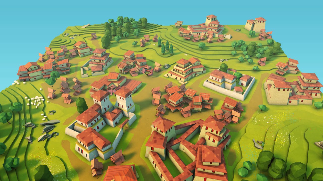
Source: https://www.youtube.com/watch?v=W7t-oqvSl6A
This article is part 2 in a series of articles and focuses exclusively on the triangulation of the contours that were extracted in part 1. Make sure to read part 1 before you read this article, because you likely won’t understand a thing otherwise.
Some of the images in this article have been recorded with the old closing algorithm
Closing contours the right way
In part 1, we implemented an algorithm to close open contours. This algorithm has one important downfall though. Look at the pictures in part 1. It’s harder to see when you don’t have any perspective, but still recognizable: In between some contours, such as the fish-like contour on the bottom left and the big one next to it, there is a gap that is not part of any contour. Those gaps are the result of the initial approach on contour closing not working correctly, because these areas should be part of a contour, but arent.
Actually, the algorithm should try to close open contours in a way that makes them be wound clockwise. The reason is, that the lower a contour gets in elevation, the larger the area is that it covers, and the higher the chance that it’s being cut in half by a super-edge. When that happens, these small, open contours are created, that are not plateaus but holes in a larger area. Instead of forming a counter clockwise wound contour, they should be excluded from a larger, clockwise wound contour. To make this happen, the closing algorithm is changed in two ways:
First, it doesn’t compute two paths along the super-edges anymore, it only computes the clockwise one and uses it.
Secondly, it doesn’t just close an open contour, because the same contour might have a second or third hole on a super-edge somewhere else. The algorithm therefore only closes a contour if it can be closed in clockwise order. If it can’t, it skips the contour and when it encounters an open contour with the same elevation, it connects the last vertex of the previous contour that has been skipped to the first vertex of the current contour, along the super-edges, including any super-corners if necessary.
The algorithm walks around the end vertices of open contours twice, because if a contour needs to be connected across the “seam” that is created by the starting point of our iteration, it cannot be closed. By walking the circle twice, this problem is solved.
The result now looks much better:

Triangulation
Now that we have extracted the contour lines, the next step is to do triangulation. We want to build two kinds of geometry:
- Side-facing walls on the outsides or insides of the contours
- Upwards-facing areas that fill the contours
N-Gon winding
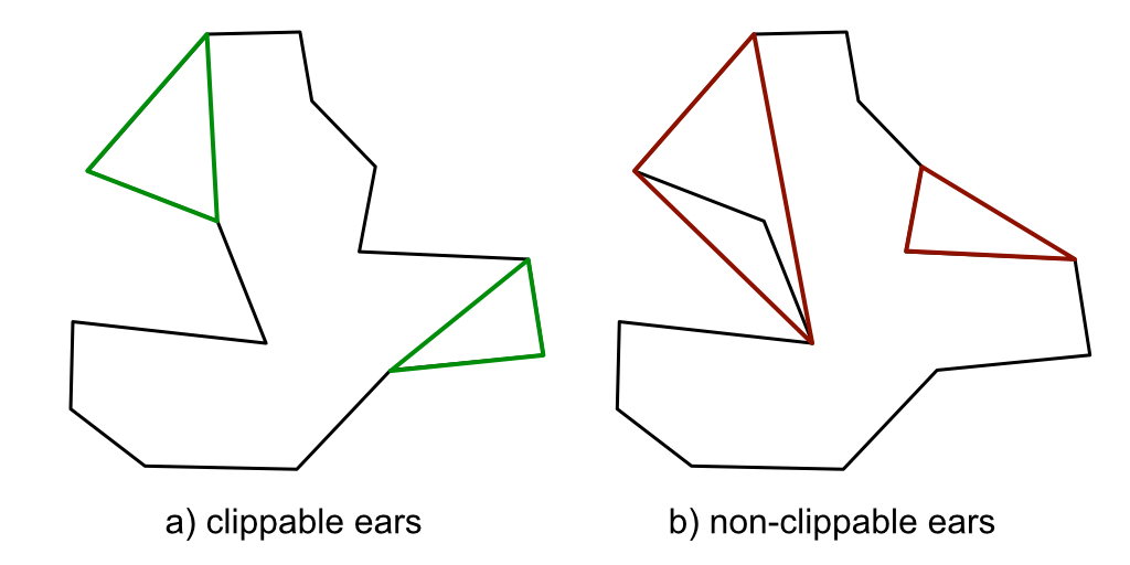
The contours represent an n-gon: A polygon with n edges, that doesn’t necessarily have to - and in our case almost certainly won’t - contain three or four edges, but many more edges. The ngons are not convex, which means they are not somewhat circular shaped, but can take many twists and turns, so triangulation isn’t as easy as connecting all of the vertices to a center point, because that would generate self-intersecting and incorrect geometry. To triangulate them, we use the so-called ear-clipping algorithm. It works by continuously clipping convex triangles off of the ngon. Convex in this case means, that the inwards-facing angle of the triangle is smaller than 180 degrees. The triangle also may not contain any other vertex of the polygon. Below you can see some examples of clippable “ears” and non-clippable ears.
In order for this algorithm to work correctly, the n-gons need to be wound (the order of the vertices in the respective per-contour lists) in a way so that it is clear on which side of the contour the geometry should be. I decided to wind the contours such that one, where the values of the noise are higher on the inside than on the outside, will be wound clockwise, and vice-versa - in other words, the right side of the contour will always be uphill. This is important, first, because in order to perform the above algorithm, we need to know what is the inside angle of three vertices, and because the order of vertices in a geometric polygon matters for rendering: Only a polygon that is ordered clockwise from the perspective of the camera will be visible.
To detect which side is uphill, I sample the noise at two points: From the center point of each edge of a contour, I sample the point perpendicular towards the right and left of the edge. If the edge is wound correctly, the value of the noise sampled at the location of the point to the right hand side must be higher than that on the left hand side. If that isn’t the case, the noise is wound incorrectly.

But that’s just half of the truth.
The truth is, that for some edges, this might give you an incorrect result. There are edges in each contour where the right hand side is lower than the left hand side, but the contour is wound correctly. These edges are the ones that lie on the super-edges, because the noise is cut in half there and therefore gives unpredictable results. So what I ended up doing is going over all of the edges of a contour, retrieve the correctness of the winding for each of them, sum up how many times it has been correct or incorrect and if it has been wound correctly more often than not, I leave it how it is, otherwise I reverse the contour. This works beautifully, although it isn’t exactly performant.
This image shows the initial winding of the contours, which is random:

And this image shows the winding after my algorithm has been applied:

As you can see, the contours are now all wound in such a way that uphill is always to the right hand side.
Walls
The walls are the sections of geometry that are side-facing instead of upwards-facing. Of course, at each contour, there must be a wall, because an elevation change takes place and we don’t want our terrain to have holes on the sides. This geometry is very easy to generate, we are walking along the now correctly-wound contours and, for each edge, build the following set of triangles:
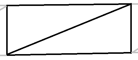
The triangles need to be wound correctly such that they are wound clockwise from the perspective of the outside of the wall. This means that, because the right hand side is uphill, the triangles must be created in counter clockwise order. This generates the following result:

Areas
Take a look at the following image. We see two contours, both wound the way we specified before, but one contour is wound in clockwise order, the other in counterclockwise order. The problem now is, that inside edges are determined by the ear-clipping algorithm by looking at the inside angles of clockwise-wound triangles. Counterclockwise contours can therefore not be triangulated with our algorithm.

This is by design! The clockwise wound contours have a very important property that differentiates them from counter-clockwise wound contours: They are plateaus, counter-clockwise wound contours are holes! What does that mean? From the top you can’t see it, but the way we implemented the winding of the contors esures that those that are wound clockwise are always plateaus that can be triangulated, while those that are counter-clockwise are holes, that have to be cut into plateaus. If you look at the image, it is clear from how the contours are wound that the left one has a lower elevation on it’s inside than on it’s outside, while the opposite is true for the right one. Now cutting holes with ear-clipping isn’t trivial, so instead of coming up with another algorithm to cut holes into geometry, we convert a plateau and it’s holes to one, clockwise-wound triangle that can subsequently be triangulated with ear-clipping. Also, for each hole, another plateau is generated by triangulating it’s inside. We take the contour, offset it downwards by the configured height of a contour, reverse it and triangulate it.
When applying the ear clipping algorithm trivially to all clockwise wound contours, we get the following result, which is already very promising:

Missing contours
You can see there is a section where there is no contour at all, resulting in a part without geometry. This part shows up because the contour it belongs to is larger than the entire chunk, meaning that it isn’t detected by the chunk at all. To fix this, we generate what I call the “floor”, a contour with four points in the four corners of the chunk with an elevation of 1f / NumContours below the lowest clockwise wound contour.
The floor is added to the array of contours so that all subsequent operations cannot distinguish it from a normally generated contour. The floor is not only needed to fix the visuals, it also serves as the parent that the highest counter clockwise wound contours cut a hole into.

Ear clipping with multiple holes
Ear clipping without holes is simple, we’ve implemented it already. Ear clipping with one hole is also not hard: For the inner contour, find the right-most vertex (highest value for x coordinate), raycast to the right and connect it to the edge that is hit by the raycast, more precisely it’s left-most end (lowest value for x coordinate).
The connection algorithm in my case returns two integers, the two indices in the outer and inner contours where the cut should be made. Then it’s as easy as walking the outer contour until the cut is reached, connect the outer vertex to the inner vertex, walk the inner contour, connect both in reverse order and finish walking the outer contour.
The problem for multiple holes is that the cuts must not intersect with other cuts or other holes and that the resulting geometry isn’t self-intersecting, because that would break the ear clipping algorithm. Here is some code and a gif:

1 | void CutHoles() |
Keep in mind the code is unoptimized, I was focusing on getting it to work first.
It first sorts holes by decreasing maximum x coordinate and then continuously raycasts until it is 100% sure that it doesn’t intersect with anything. Then the cuts are made and ear clipping is applied.
Final result
The final result with the complete algorithm looks like this:
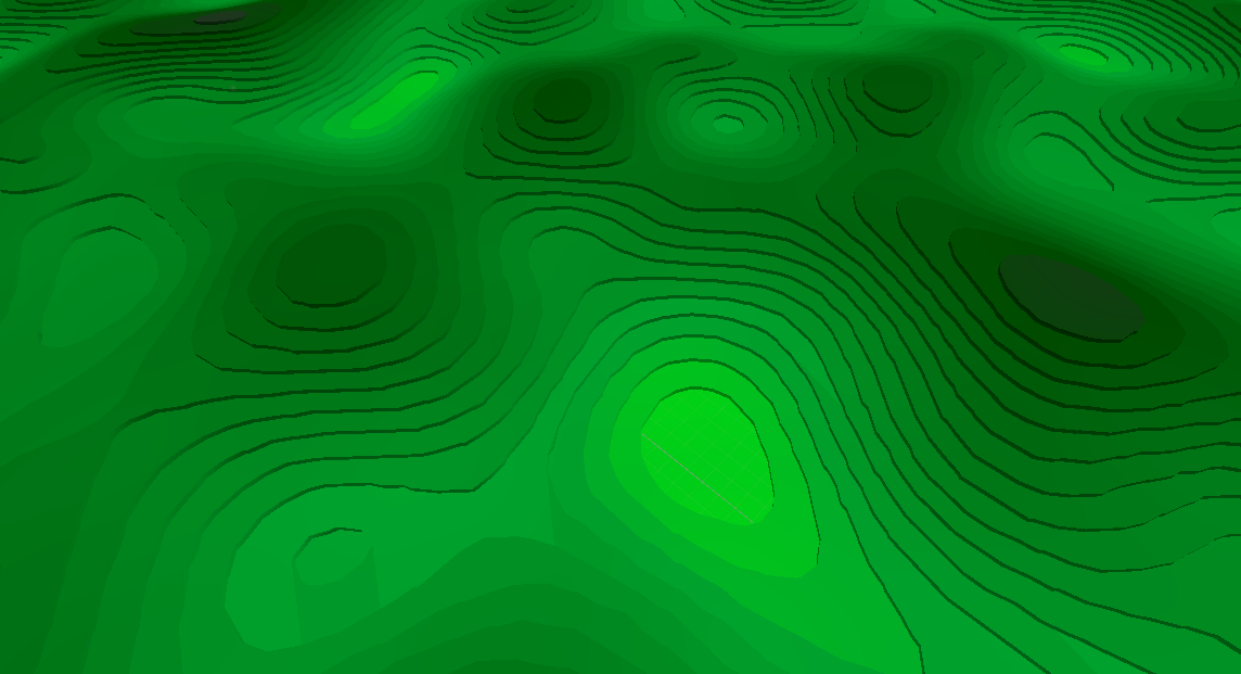
You can see there are still issues with normals.
This article is WIP and I have not yet come around to do the rest. Check back next week.
Thoughts or questions? Leave me a comment!